Welcome to the Cadillac V-Series Forums!

Jacking up your Blackwing

Looking at the photos in the service manual and that language confirms for me that your lift pads should be next to the seam towards the centerline of the car, not under it.
Agree. That's what the picture looks like to me.

Also, in post 14 Mirza says to place blocks "behind the pinch flange" which I interpret to mean inboard (I also assume he is describing a 4 - not sure how different a 5 is)

The fact that there's over 300 posts on this is proof how poor the factory documentation is. They could spend a little more and get a photo of an actual car instead of a poorly chosen black and white CAD model that isn't zoomed in enough show the actual lift point
 
Last edited:
Agree. That's what the picture looks like to me.

Also, in post 14 Mirza says to place blocks "behind the pinch flange" which I interpret to mean inboard (I also assume he is describing a 4 - not sure how different a 5 is)

The fact that there's over 300 posts on this is proof how poor the factory documentation is. They could spend a little more and get a photo of an actual car instead of a poorly chosen black and white CAD model that isn't zoomed in enough show the actual lift point
unfortunately their motivation is to drive you to the dealership for service, not to make it easy for you to work on your own car.
 
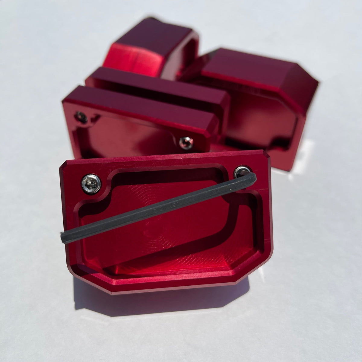
I hate to keep extending this thread, but I installed the ZL1 Add-on‘s Stealth Lift pads recommended for the 5BW and they interfere with a piece of black plastic in the pocket of the lift point. Not sure what exactly the piece of plastic is attached to, but when I press it upwards it slightly flexes the lower body panel and wheel well panel. It didn’t seem like it does enough to warrant doing anything with it, but maybe I could notch it with a dremel tool if needed.

Did anyone/everyone have the same issue on the 5BW? Did you do anything about it?

Image for reference:
22E88854-0BC5-4880-A189-31E9C38DC17E.jpeg
 
I hate to keep extending this thread, but I installed the ZL1 Add-on‘s Stealth Lift pads recommended for the 5BW and they interfere with a piece of black plastic in the pocket of the lift point. Not sure what exactly the piece of plastic is attached to, but when I press it upwards it slightly flexes the lower body panel and wheel well panel. It didn’t seem like it does enough to warrant doing anything with it, but maybe I could notch it with a dremel tool if needed.

Did anyone/everyone have the same issue on the 5BW? Did you do anything about it?

Image for reference:
View attachment 22727
I had the same issue so I demel it out around the lift points. Helps the thing sit flush.
 
I hate to keep extending this thread, but I installed the ZL1 Add-on‘s Stealth Lift pads recommended for the 5BW and they interfere with a piece of black plastic in the pocket of the lift point. Not sure what exactly the piece of plastic is attached to, but when I press it upwards it slightly flexes the lower body panel and wheel well panel. It didn’t seem like it does enough to warrant doing anything with it, but maybe I could notch it with a dremel tool if needed.

Did anyone/everyone have the same issue on the 5BW? Did you do anything about it?

Image for reference:
View attachment 22727
The plastic gets pushed up a little and I didn’t do anything about it.
 
To me the disconnect was with the version of the lift point guys were using. Originally, ZL1addons was offering the original and the stealth pad.

After I sent them pics, videos and measurements showing the original point DOES NOT FIT, they pulled it off the website as compatible with CT5. The stealth pad has a shallower cutout for the pinch weld and even though it contacts the plastic skirt, it still fully seats on the pinch weld. Making it safe to use.
 
I know, I stated that at least three times already in this thread and so did others. I understand most people don’t want to read the entire thread so this one is like a record that repeats and never ends

To me the disconnect was with the version of the lift point guys were using. Originally, ZL1addons was offering the original and the stealth pad.

After I sent them pics, videos and measurements showing the original point DOES NOT FIT, they pulled it off the website as compatible with CT5. The stealth pad has a shallower cutout for the pinch weld and even though it contacts the plastic skirt, it still fully seats on the pinch weld. Making it safe to use.
Thanks for that because that really helps as I was wondering what was going on and I am looking to get the lift pads and it seemed confusing.
 
Do those lift puck blocks exist for the 4BW?
Just because the language has gotten us in trouble in this thread...

There is a MagPad (with puck) that is universal with pinch welds and works with floor jacks/lifts


And a permanently installed lift pad


There is no lift pad for the CT4.
 
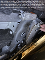
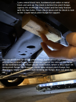
This is still going, I will try to take some pictures of my CT4 explain. I don't lift either the front or rear on the pinch flange, CT4 or CT5.

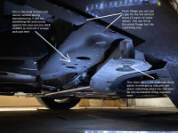
Front: If you take a close look at the pinch flange, you will notice that there is a reinforcement part right in the jack opening between the two panels, so the flange actually has 3 layers of metal there. That middle part is a big vertical bracket, sandwiched, that goes vertically up to body for reinforcement as a lift point (you can't see it, internal to rocker). Additionally, you will notice the plastic from the rocker on the outer side of the flange which makes me not lift there with the aftermarket aids (Zl1 add ons etc.). From a plant build standpoint, if you look on the inside of the car behind the aluminum shear panel, there is two round holes about 1-2" in diameter, those are body features used to hold the entire car fully assembled up in the air through the factory, so the pinch flange is not used while the manufacturing is conducted of our cars (body comes in bare on those, cars comes off with tires doors and everything from those onto a platform for first touch on tires at end of line).

So, I lift just inboard of the pinch flange where that 3 layer metal is, I place a block of hardwood/aluminum, jam it against the front shear panel, now that block is locked by the pinch flange, by the shear panel bolt area and the inboard two hole feature, it can NOT slide or move and when you lift you are still engaging the vertical 3rd layer of the pinch flange, some of the plant body feature. Not far away from that, more forward, is another vertical bracket inside the rocker as well that provides a lot of structure, you just don't see it.

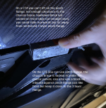
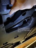
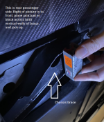
Rear: Similar body features for the manufacturing plant exist on rear, just closer to the pinch flange inboard wise. From a lifting standpoint the 4 and 5 differ on the rear. On the 4 the structural cradle brace to body blocks the pinch flange area, so you lift the 4 by placing jack or whatever across the two vertical walls of the brace just under the bolt or next to the pinch flange area, not far off. On the CT5 the rear brace is a bit different so you have room to lift on the pinch flange but you can lift just like the 4 on the brace, placing the jack stand on a big flat body feature just inboard of the pinch flange. You can also jack here if you have a block or room with your jack.

Long story shorty short, the pinch flanges are reinforced and work great if you have an aftermarket block or jack that pushes against IT (I don't enjoy bending them with jacks that have wheels, which is why I DO NOT lift there) but with our rockers, carbon fiber and other features make other areas easier for me. The rear is super simple and clear, use the chassis brace, done.

Hope this helps and all the best with the cars, I enjoy driving my 4 more and more and am already itching for another track day next year!
Pics will make this a thread-ender and (hopefully) put an end to all the back and forth. Thank you, Mirza.
 
Sorry took so long team, crawled under today got some pics on my personal CT4-V Blackwing. I will start with rear.
 

Attachments

  • CT4 Rear 3.png
    CT4 Rear 3.png
    698.8 KB · Views: 321
  • CT4 Rear 2 (1).png
    CT4 Rear 2 (1).png
    1 MB · Views: 318
  • CT4 Rear 2 (2).png
    CT4 Rear 2 (2).png
    714.8 KB · Views: 317
Last edited:
Alright front is next: I don't know why the forum lists them 3-1 in order but it doesn't matter you get the picture. Hope this helps every body, from the pictures you can see areas where I put a jack stand usually as well in the front. I will also utilize jack stands close to the lower link attachments on the front craddle. When I am under the car I always have jacks on each side plus at least 2 jack stands, usually 4 in the front.

Total 6 jack stands and the 4 jacks, I know its overkill but my son and daughter crawl under there too so I can show them stuff and teach them to wrench. Bottom line my head and body is never under car without jack stands on each side of my body and especially head.

Be safe, take the time to think before you work while under car, if you have any doubts get out, get more jack stands or worst case slide the wheels under car too. Take a few seconds, think about what your doing and proceed, don't rush.
 

Attachments

  • CT4 Front 3.png
    CT4 Front 3.png
    1.2 MB · Views: 323
  • CT4 Front 2.png
    CT4 Front 2.png
    968.6 KB · Views: 324
  • CT4 Front 1.png
    CT4 Front 1.png
    1.2 MB · Views: 318
@Mirza Grebovic This is amazing - thank you so much for sharing. Exactly what this thread needed. And very timely as well for me as I embark on my first wrenching job ever on a car (replace brake pads) but couldn’t figure out how to safely lift car.

Curious what the measurements on that wood block are (particularly the width going from pinch weld to the body feature with the holes).

Thanks again!
 
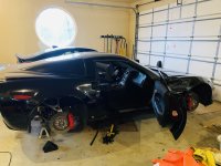
That was a 2x2 but some cheap crap around garage. Get hardwood. My jacks have a 4" pad, so part of pad is under pinch flange in case something gives. But the wood doesnt tear up the coatings. Here is my other ride that I lifted today for some work, 4 stands on hockey pucks actually.
 

Attachments

  • IMG_7258.jpeg
    IMG_7258.jpeg
    2.9 MB · Views: 166
Alright front is next: I don't know why the forum lists them 3-1 in order but it doesn't matter you get the picture. Hope this helps every body, from the pictures you can see areas where I put a jack stand usually as well in the front. I will also utilize jack stands close to the lower link attachments on the front craddle. When I am under the car I always have jacks on each side plus at least 2 jack stands, usually 4 in the front.

Total 6 jack stands and the 4 jacks, I know its overkill but my son and daughter crawl under there too so I can show them stuff and teach them to wrench. Bottom line my head and body is never under car without jack stands on each side of my body and especially head.

Be safe, take the time to think before you work while under car, if you have any doubts get out, get more jack stands or worst case slide the wheels under car too. Take a few seconds, think about what your doing and proceed, don't rush.
My local dealer has crushed the #%*& out of the front area where the 2 assembly line lift holes are on my CT5V. :( I have only used the pinch welds for lifting the car in my garage because I know that other area is soft. I'll discuss that with them next time I have to take it in. This is what causes low dealer confidence.
 
My local dealer has crushed the #%*& out of the front area where the 2 assembly line lift holes are on my CT5V. :( I have only used the pinch welds for lifting the car in my garage because I know that other area is soft. I'll discuss that with them next time I have to take it in. This is what causes low dealer confidence.
tumblr_a3a2dc235f7fc19984383d261eee48fe_dc328d7f_540.gif
 

Win 2 Supercharged Cadillacs!

Win both supercharged Cadillac Vs!

Supporting Vendors

Exhibitions of Speed

Signature Wheels

Taput Tunning LLC

V-Series Marketplace

Advertise with the Cadillac V-Net!

Torque Shop

Our Partners

Back
Top Bottom