2016 - 2019 Cadillac CTS-V: Service Bulletin: #18-NA-291: Reduced Performance, Reduced Power, Engine Misfire After Charge Air Cooler Service
Estimated Reading Time: 8 Minutes#18-NA-291: Reduced Performance, Reduced Power, Engine Misfire, Malfunction Indicator Lamp (MIL) Illuminated - DTC P0300 Set After Service or Replacement of Charge Air Cooler - (Oct 29, 2020)
| Subject: | Reduced Performance, Reduced Power, Engine Misfire, Malfunction Indicator Lamp (MIL) Illuminated - DTC P0300 Set After Service or Replacement of Charge Air Cooler |
|
Brand: |
Model: |
Model Year: |
VIN: |
Engine: |
Transmission: |
||
|---|---|---|---|---|---|---|---|
|
from |
to |
from |
to |
||||
|
Cadillac |
CTS |
2016 |
2019 |
— |
— |
6.2L (RPO LT4) |
— |
|
Chevrolet |
Camaro |
2017 |
2021 |
||||
|
Involved Region or Country |
North America, Europe, Russia, Middle East, Israel, Argentina, Brazil, Bolivia, Chile, Colombia, Ecuador, Paraguay, Peru, Uruguay, Japan, GM Korea Company, Cadillac Korea (South Korea), China, Taiwan, Philippines |
|
Condition |
Some customers may comment on one or more of the following conditions while track driving during high ambient temperatures:
During diagnosis, a technician may find DTC P0300 (Engine Misfire Detected) set or stored in the Engine Control Module (ECM). |
|
Cause |
This condition may be caused by the supercharger’s charge air cooler system not being properly evacuated and filled after service or replacement of the charge air cooler. |
|
Correction |
If you encounter a vehicle with the above concern, refer to the Service Procedure below. |
-
Service Procedure
-
Important: This procedure must be performed when the intercooler system is cool.
Special Tools
Any time that the supercharger’s cooling system is replaced, removed or separated from the engine, it must be properly drained and filled using the following special tools:
- GE-26568 Coolant and Battery Fluid Tester
- GE-47716 Vac-N-Fill Coolant Refill Tool
- GE-52079 Tool, Coolant System Fill
- GE-52079-10 Adapter, Coolant System Fill Tool
Important: It may be necessary to replace the system fill port in order for service tool GE-52079 and adapter 52079-10 can be used to bleed the charge air cooler system. The new fill port will remain installed after the bleed procedure is completed.
- Evacuate .5 qt (.5 L) of coolant from the system.
- Place a rag under the fill port to catch any coolant that may spill when the system is opened.
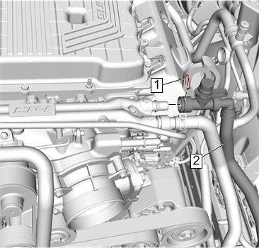
- Remove the charge air cooler coolant hose retainer (1).
- Loosen the Schrader valve port hose clamp and position away from port.
- Separate the Schrader valve port from the hose (2).
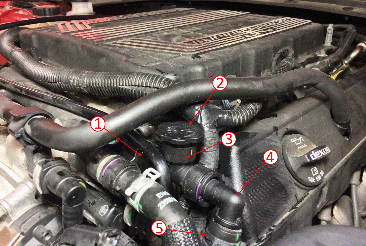
- Assemble the new fill port (3) with cap (2) and 90 degree elbow (4).
- Install the fill port into the charge air cooler coolant hose and secure the hose clamp (5).
- Install the fill port to the engine coolant manifold (1).
Important: To prevent boiling of the coolant/water mixture in the vehicles cooling system, do not apply vacuum to a cooling system above 49°C (120°F). The tool will not operate properly when the coolant is boiling.
Note: The system will be properly bled when the fluid appears clear in the reservoir.
- Install a battery tender/charger.
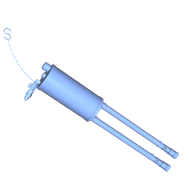
- Add .5 qt (.5 L) of coolant to the system through service tool GE-52079.
- Attach the MDI to vehicle.
Note: It is best for the hoses on GE-52079 Tool, Coolant System Fill to be as straight and vertical as possible for adequate flow. The GE-52079 Tool, Coolant System Fill reservoir should be as high as possible for the hoses to be straight. Zip ties can be used to fasten the chain links together in order to shorten the support chain.
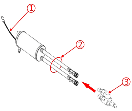
- Attach GE-52079 Tool, Coolant System Fill lines (2) to GE-52079-10 Adapter, Coolant System Fill Tool (3).
Important: When hanging the tank, be sure to protect the hood surface so the chain/hook does not damage the hood surface.
- Utilizing the support chain (1), affix the GE-52079 tank to the hood.
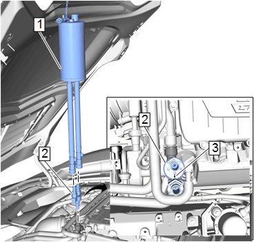
- Insert the other end of the GE-52079-10 adapter (2) into the fill port tee.
- Ensure the arrow (3) on the GE-52079-10 adapter is parallel with the charge air cooler coolant hose pointing away from the supercharger inlet.
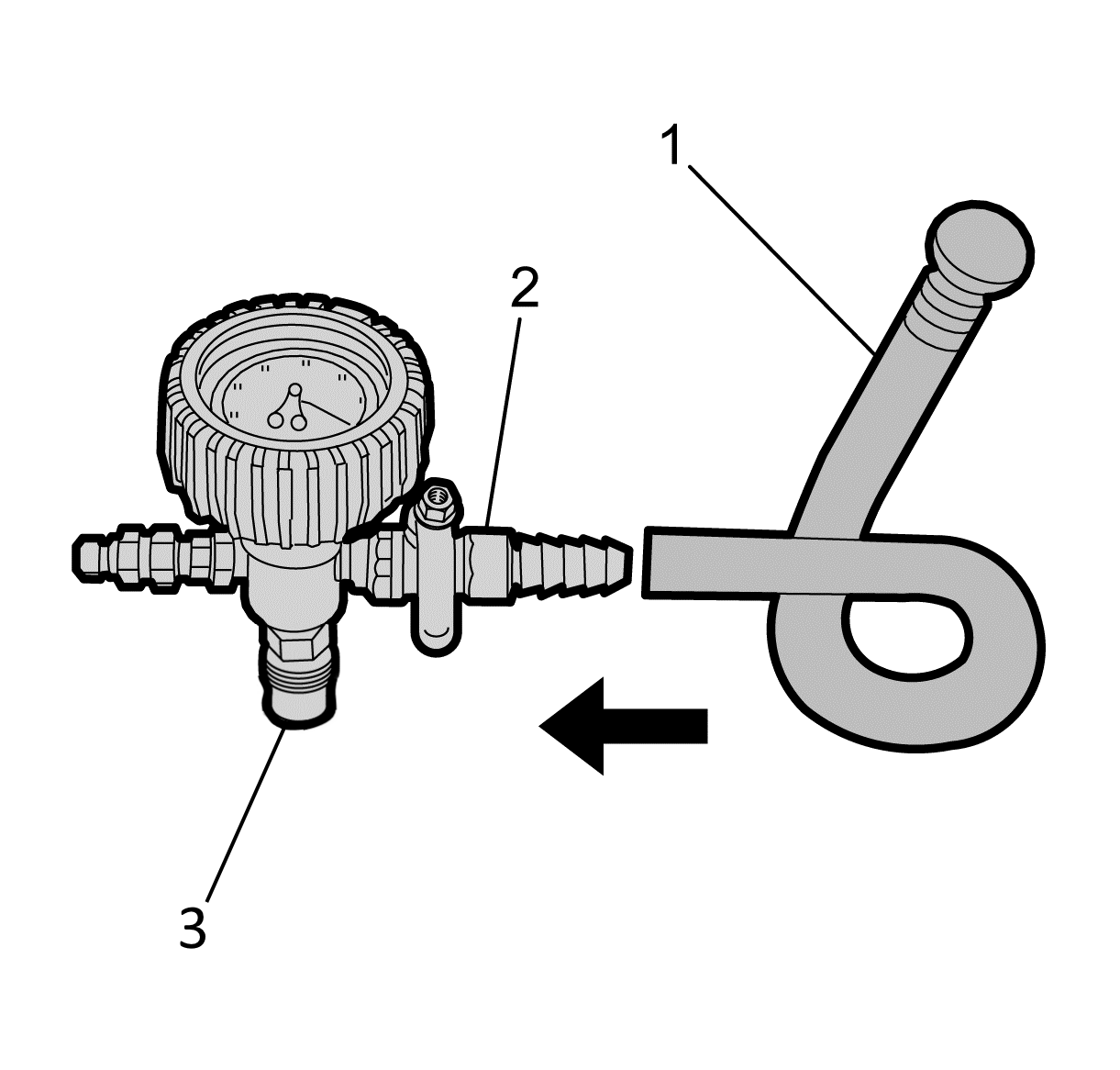
- Attach the vacuum gauge lower port (3) to top port of the GE-52079 tank.
- Attach the fill hose (1) to the barb fitting (2) on the vacuum gauge assembly ensuring that the valve is closed.
Note: Use a 50/50 mixture of DEX-COOL antifreeze and clean, drinkable water. Always use more coolant than necessary. This will eliminate air from being drawn into the cooling system.
- Using GE-26568 Coolant and Battery Tester, check the concentration of the coolant/water mixture.
- Prior to installing the vacuum tank onto the graduated reservoir, ensure that the drain valve located on the bottom of the tank is closed.
- Pour the coolant mixture into the graduated reservoir (1).
- Place the fill hose from the vacuum gauge, into the graduated reservoir.
Note: Prior to installing the vacuum tank onto the graduated reservoir, ensure that the drain valve located on the bottom of the tank is closed.
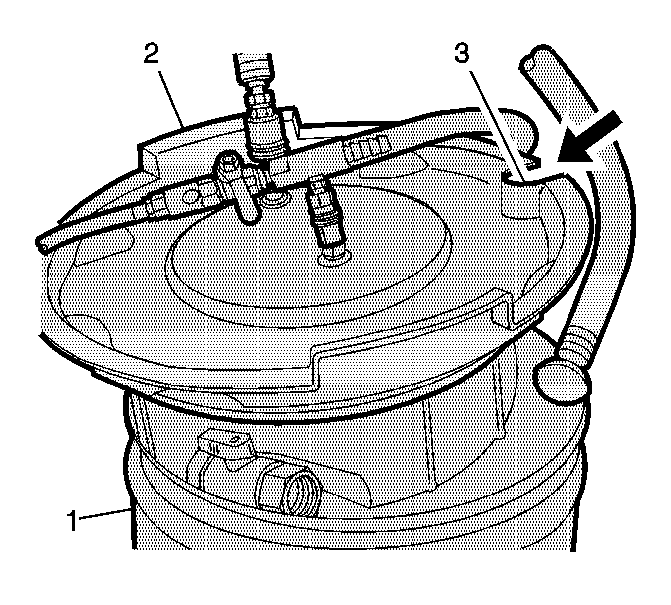
- Install the vacuum tank (2) on the graduated reservoir with the fill hose routed through the cut-out area (3) in the vacuum tank.
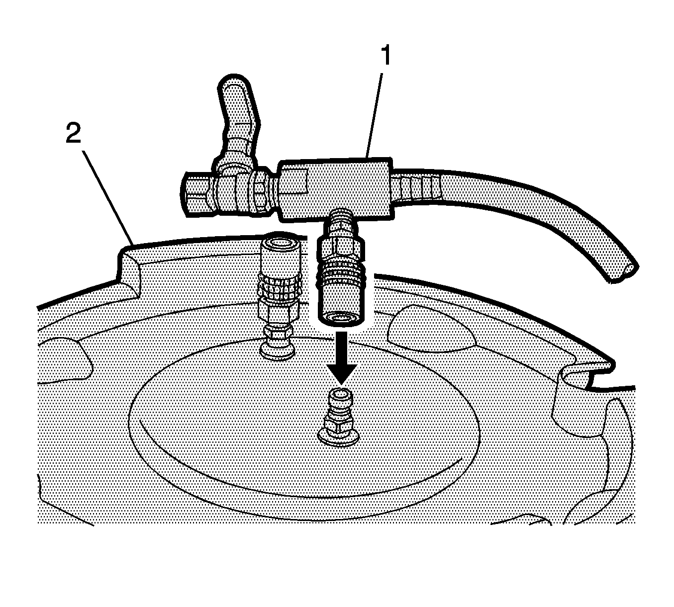
- Attach the venturi assembly (1) to the vacuum tank (2).
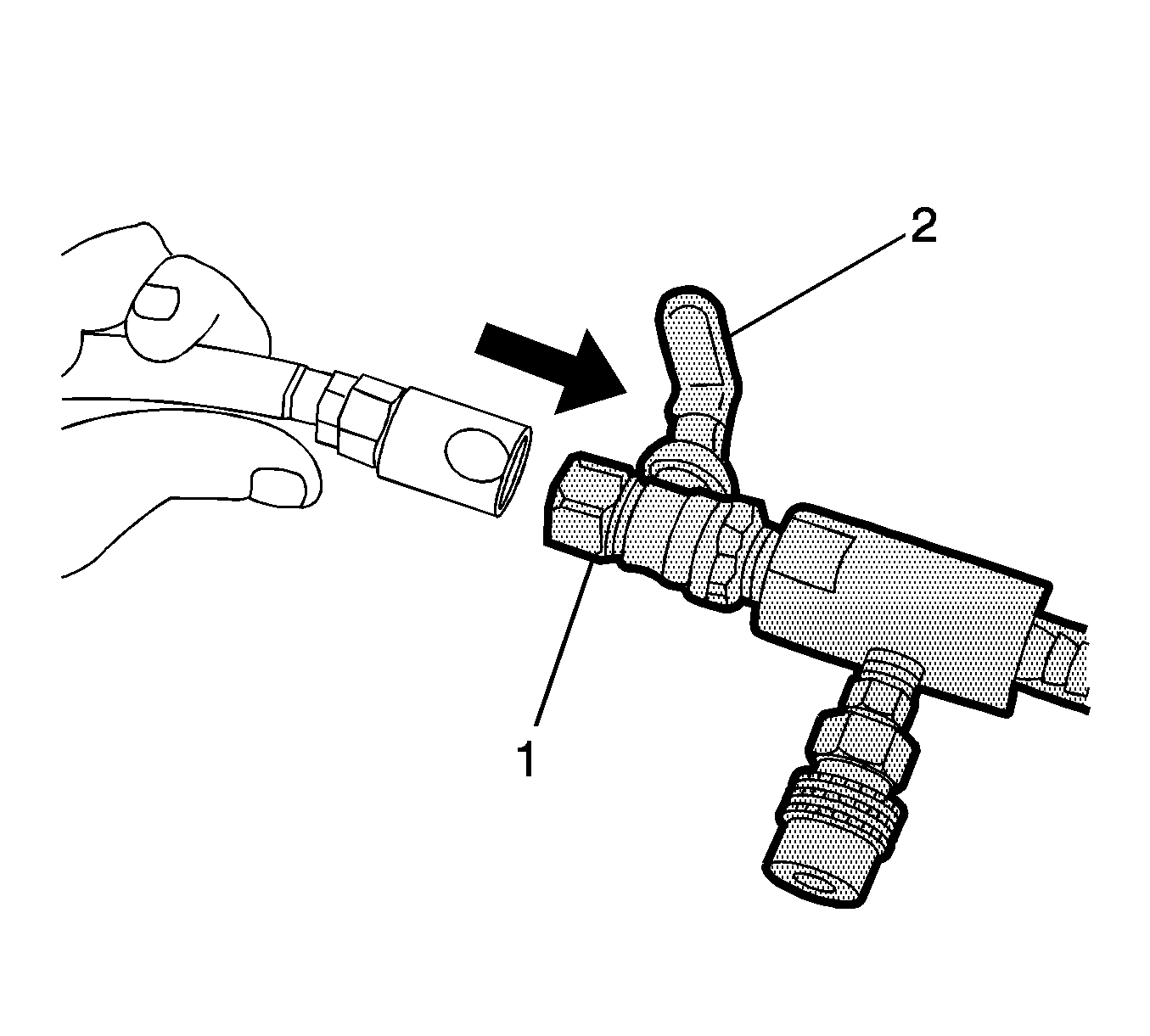
- Attach a shop air hose to the venturi assembly (1).
- Ensure the valve (2) on the venturi assembly is closed.
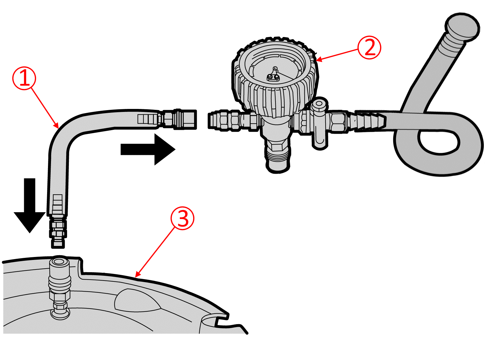
- Attach the vacuum hose (1) to the vacuum gauge assembly (2) and the vacuum tank (3).
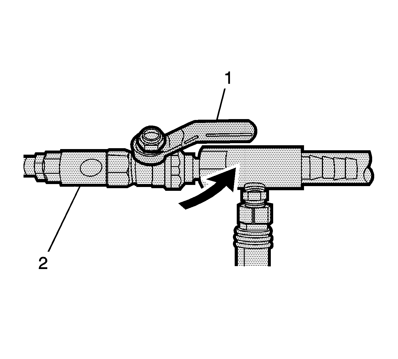
- Open the valve (1) on the venturi assembly (2).
- The vacuum gauge will begin to rise and a hissing noise will be present.
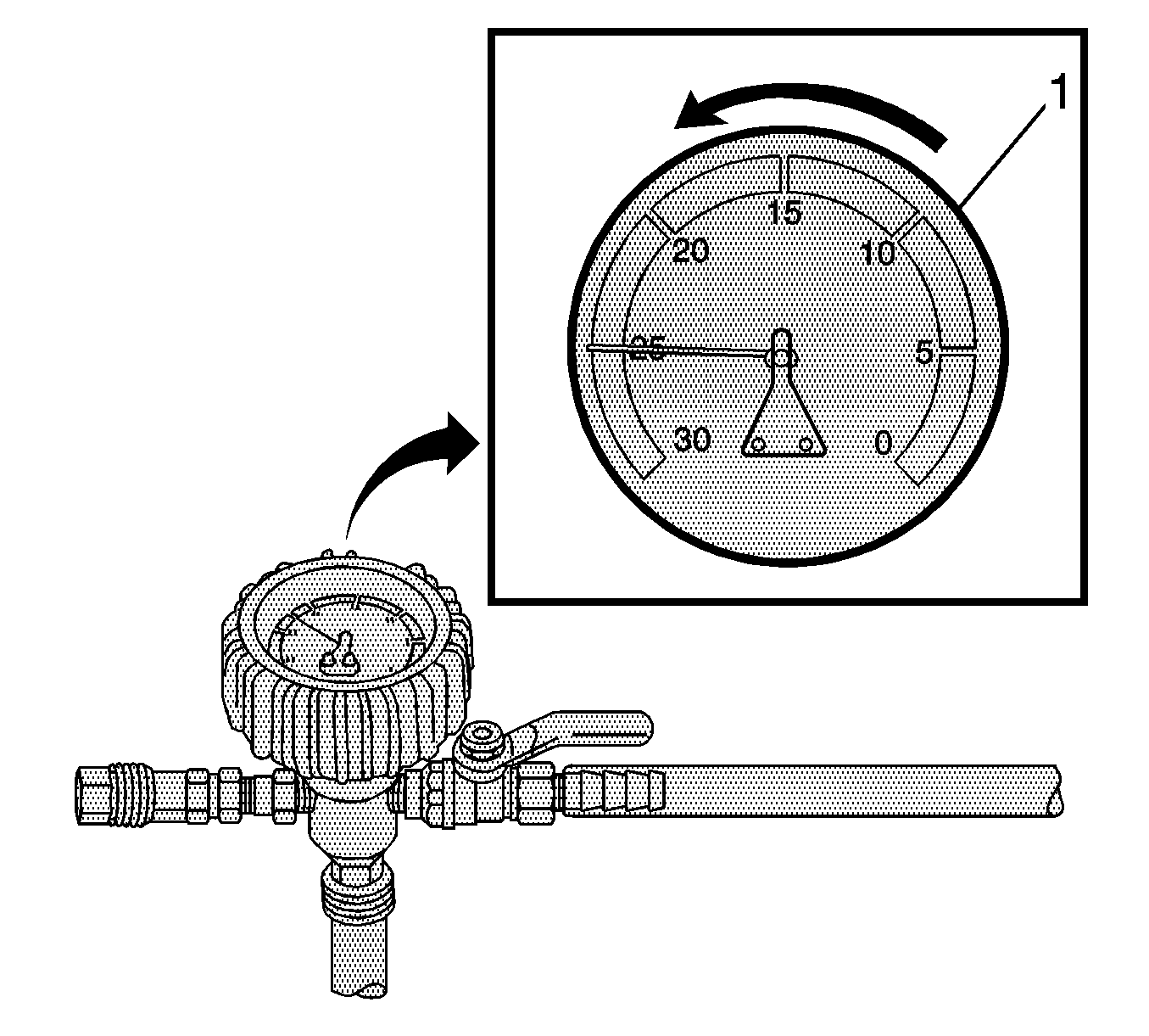
- Continue to draw vacuum until the needle stops rising (1). This should be 610-660 mm Hg (24-26 in Hg).
- Cooling hoses may start to collapse. This is normal due to vacuum draw.
- To aid in the fill process, position the graduated reservoir above the coolant fill port.
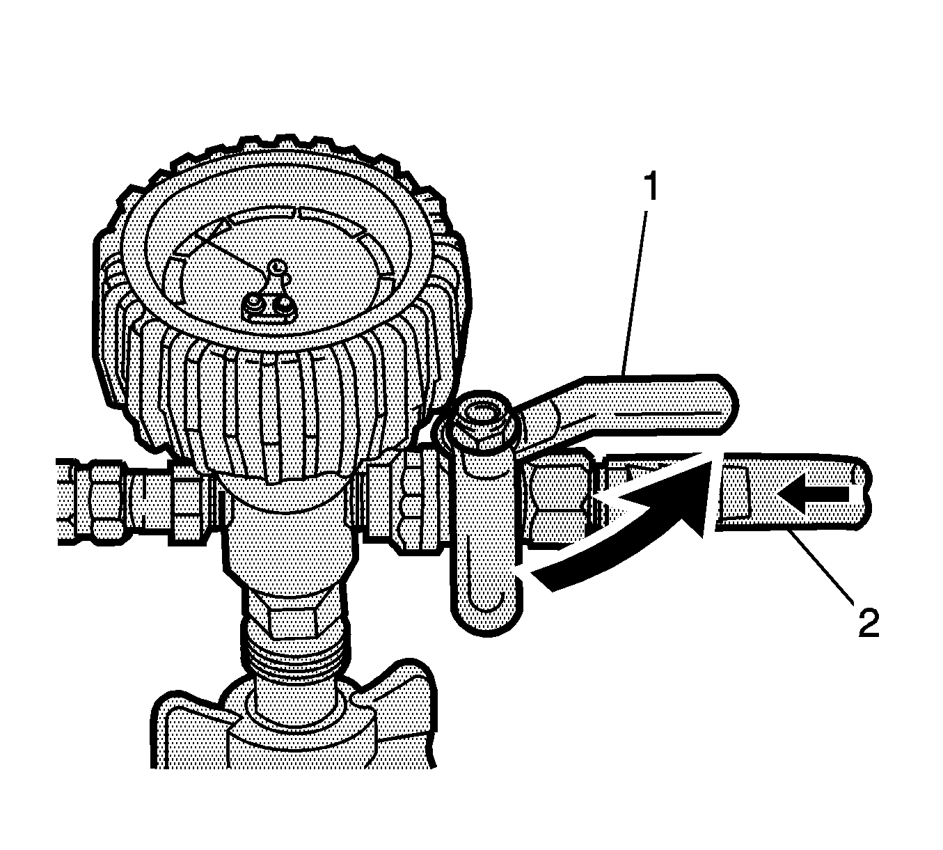
- Slowly open the valve (1) on the vacuum gauge assembly (2).
- When the coolant reaches the top of the fill hose, close the valve. This will eliminate air from the fill hose.
- Close the valve on the venturi assembly:
- If there is a suspected leak in the cooling system, allow the system to stabilize under vacuum and monitor for vacuum loss.
- If vacuum loss is observed, refer to Loss of Coolant in SI.
- Open the valve on the vacuum gauge assembly. The vacuum gauge will drop as coolant is drawn into the system.
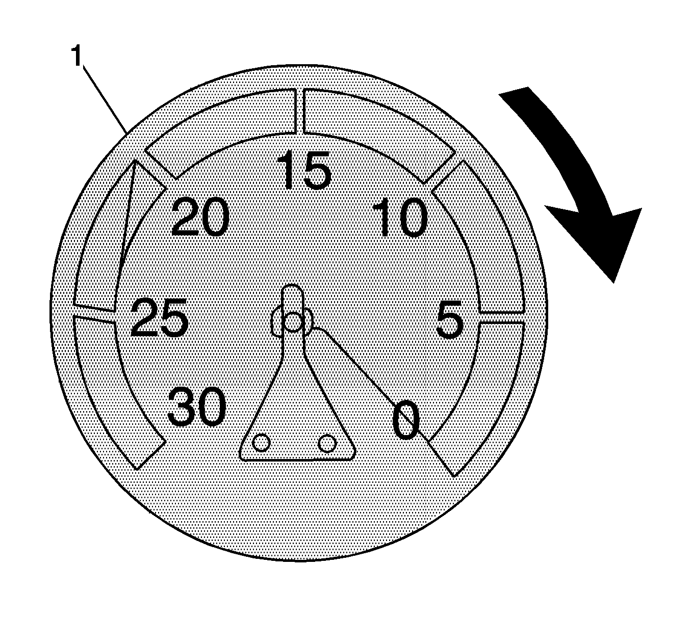
- Once the vacuum gauge (1) reaches zero, close the valve on the vacuum gauge assembly and repeat steps 10-16 at least two more times.
- Close the valve on the venturi assembly.
- Detach the vacuum gauge assembly from GE-47716 Vac-N-Fill Coolant Refill Tool from GE-52079 Tool, Coolant System Fill.
- Detach the vacuum hose from the vacuum gauge assembly.
- Open the drain valve located on the bottom of the tank to drain coolant from the vacuum tank into a suitable container for disposal.
Note: The charge air cooler coolant pump will shut off if it sucks in air. If this occurs, the system must be drawn into a vacuum to add more coolant. This is a much quicker way to fill the air pockets as opposed to just adding coolant from the top of the GE-52079 Tool, Coolant System Fill reservoir. If the system is not drawn into a vacuum after the charge air cooler coolant pump shuts off, this procedure will only take longer if coolant is just poured in from the top.
- Unscrew the fill cap on top of the GE-52079 Tool, Coolant System Fill, to allow the system to vent.
- Do not remove the cap completely, unscrew approximately 2-3 rotations.
- Connect a scan tool to the vehicle.
- Connect a battery charger to keep the battery charged during the de-aerating procedure.
- Turn the ignition to the ON position, with the engine OFF.
- Using the scan tool, navigate to special functions in the Engine Cooling section and command the charge air cooler coolant pump on.
- Allow the charge air cooler coolant pump to run continuously.
- The coolant will be opaque in the GE-52079 reservoir to begin with.
- The coolant level will gradually decrease in the GE-52079 reservoir as the system de-aerates.
- The level in GE-52079 reservoir should always be more than half full.
- Too low of a coolant level will cause turbulence, which will make it difficult to remove the air from the system.
- Observe the coolant state of flow:
- This will be caused by the charge air cooler coolant pump sucking in air.
- If coolant flow is noticed to have stopped, the charge air cooler coolant pump has shut off.
- If this occurs, repeat the Vac-N-Fill procedure to pull the system into a vacuum to remove air, followed by adding more coolant as needed.
- Once the level is stabilized just over the halfway point, command the charge air cooler coolant pump back on and continue.
- Continue to observe the coolant in the GE-52079 reservoir:
- Once the coolant is flowing clear with absolutely no air bubbles to be seen, the procedure is complete.
- Using the scan tool, command the charge air cooler coolant pump off.
- Disconnect the scan tool from the vehicle.
-
Parts Information
-
Causal Part
Description
Part Number
Qty
N/A
HOSE, CHRG AIR CLR COOL
84344455
1
N/A
CONNECTOR, CHRG AIR CLR COOL HOSE
84344461
1
-
Warranty Information
-
For vehicles repaired under the Bumper-to-Bumper coverage (Canada Base Warranty coverage), use the following labor operation. Reference the Applicable Warranties section of Investigate Vehicle History (IVH) for coverage information.
Labor Operation
Description
Labor Time
4086558*
Vac-N-Fill Procedure
0.7 hr
*This is a unique Labor Operation for bulletin use only.
|
Version |
3 |
|
Modified |
Released September 25, 2018 December 05, 2018 – Updated the CTS Model Year and added Parts Information section. October 29, 2020 – Added the 2020-2021 Model Years to Camaro, updated the Involved Region or Country section and clarified the Cause section. |